Converting a 1962 Cordovox Accordion Amp to a guitar amp…
A brief build summary:
- Tone Generator Cabinet gutted.
- -Components parted out and scrapped.
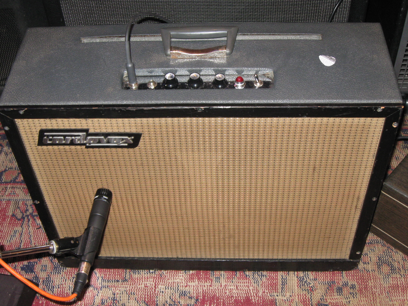
- Tone Generator Cabinet used for build.
- -Chosen for existing control panel cutout.
- -Cabinet modified with 2×12 speaker baffle.
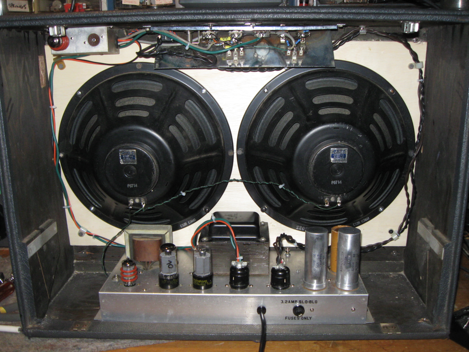
- Original Jensen C12R Speakers relocated.
- Amplifier
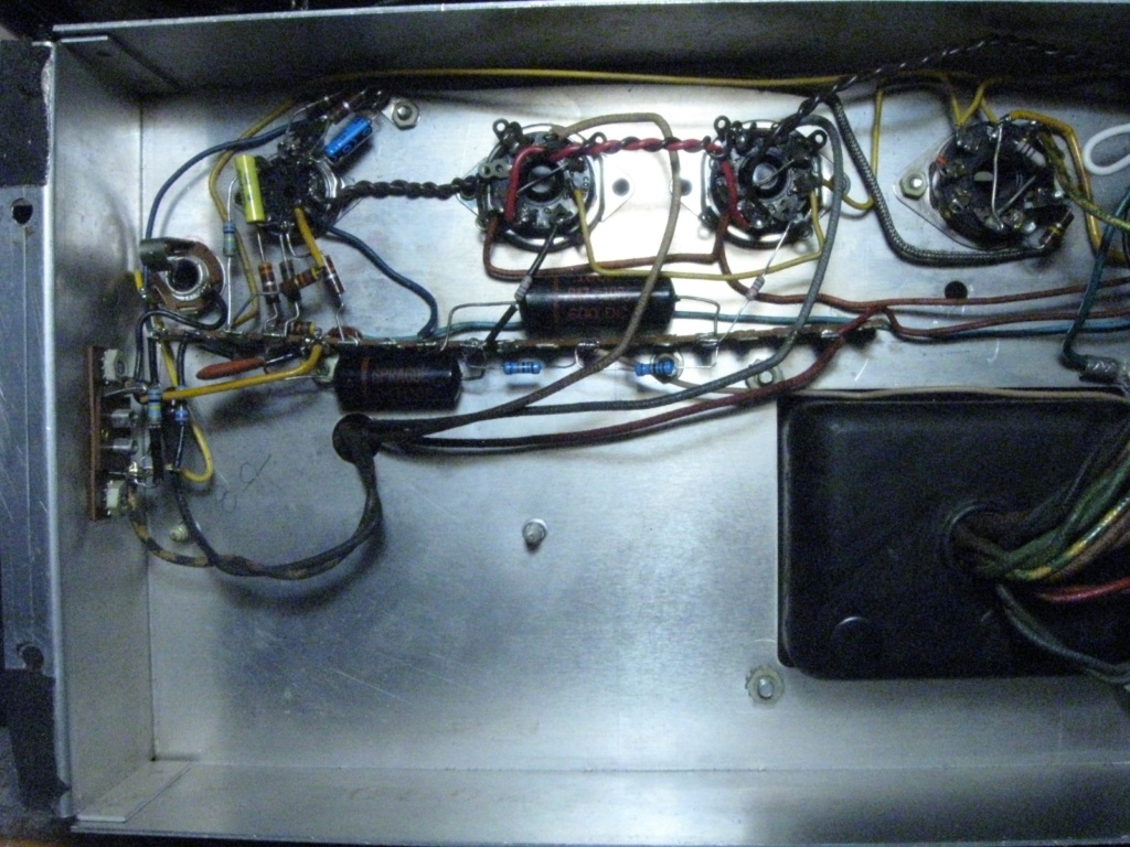
- -Chassis moved to tone generator cabinet.
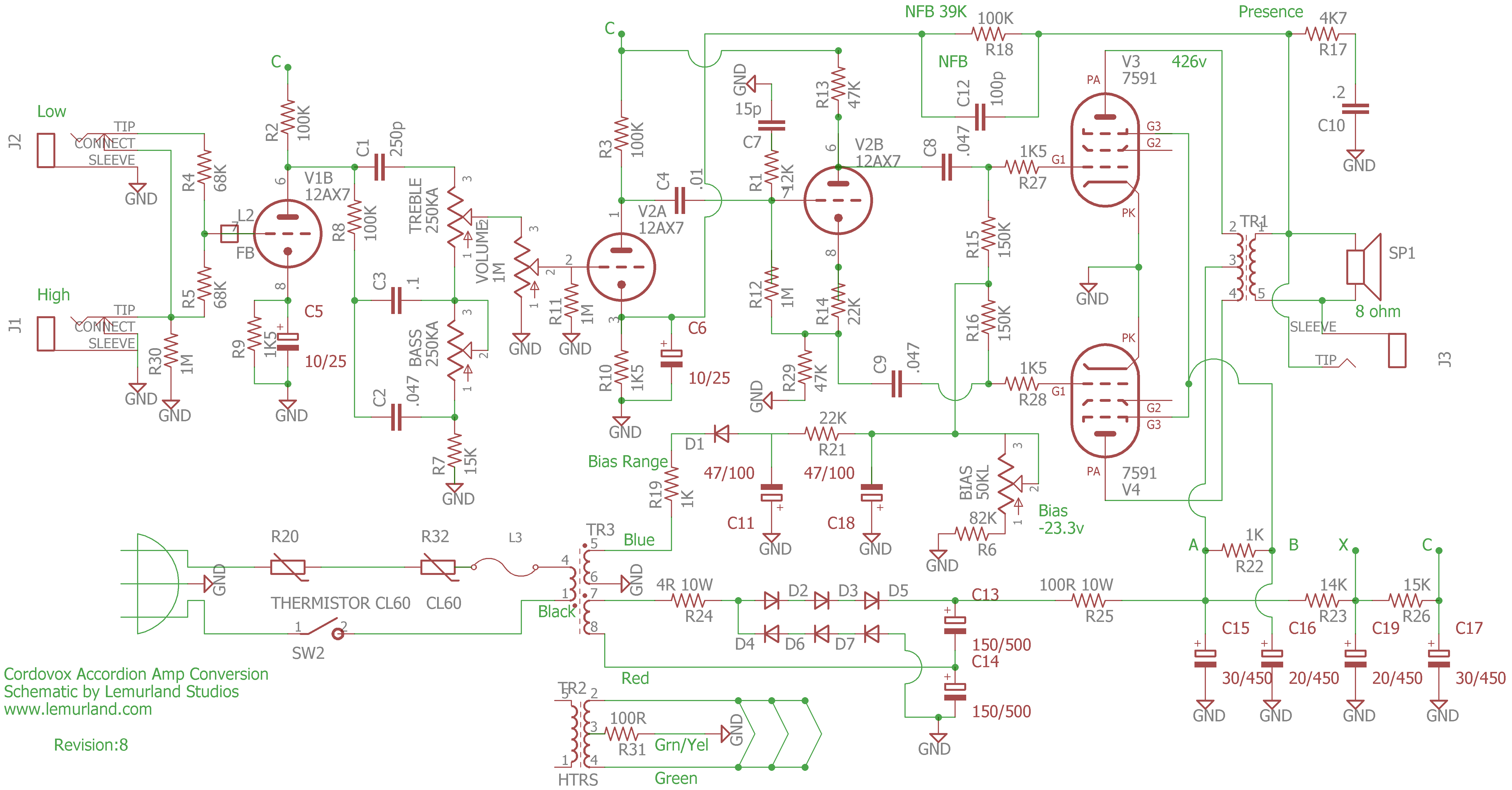
- -Circuit traced and redesigned. Schematic below.
- -Amp rebuilt.
- -Extraneous components removed.
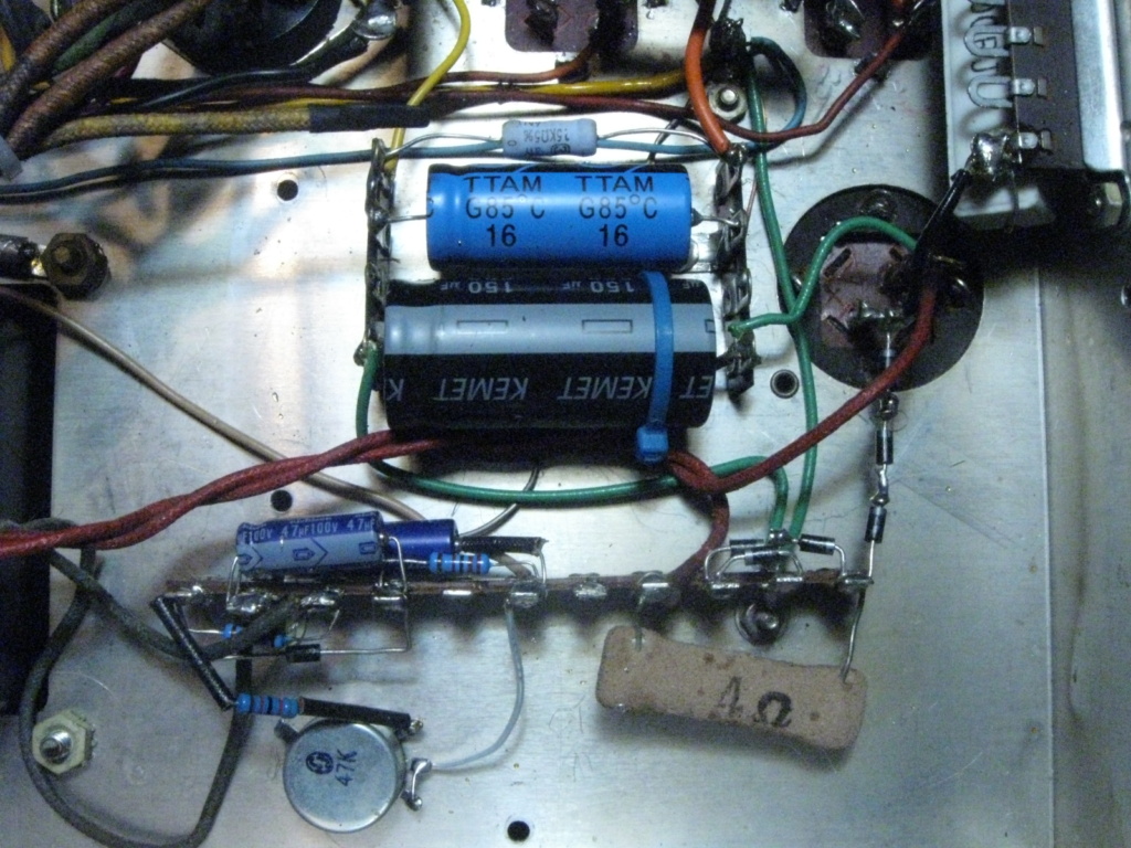
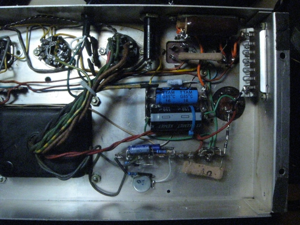
- -Multi-section can capacitors rebuilt .
- 30uf cap and 15k resistor from preamp filter section moved to chassis.
- -This section originally located on tone generator board.
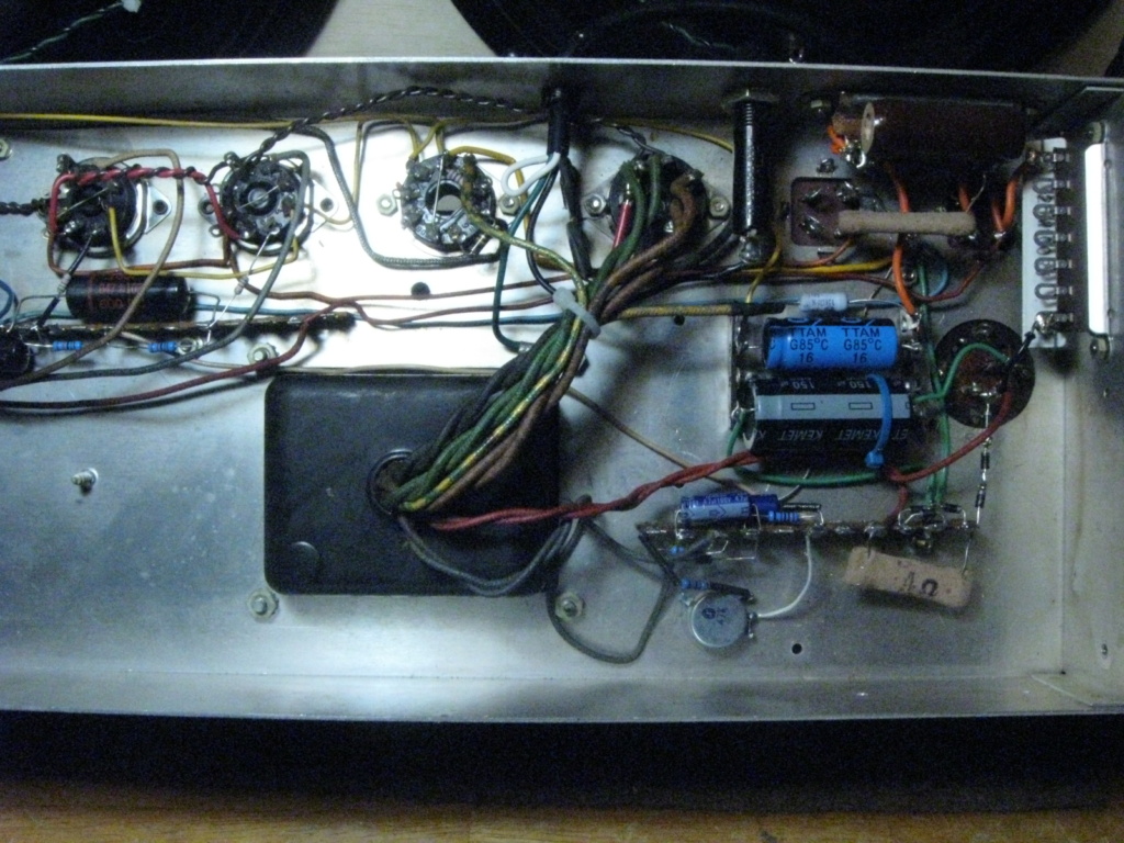
- -Terminal strips added for mounting
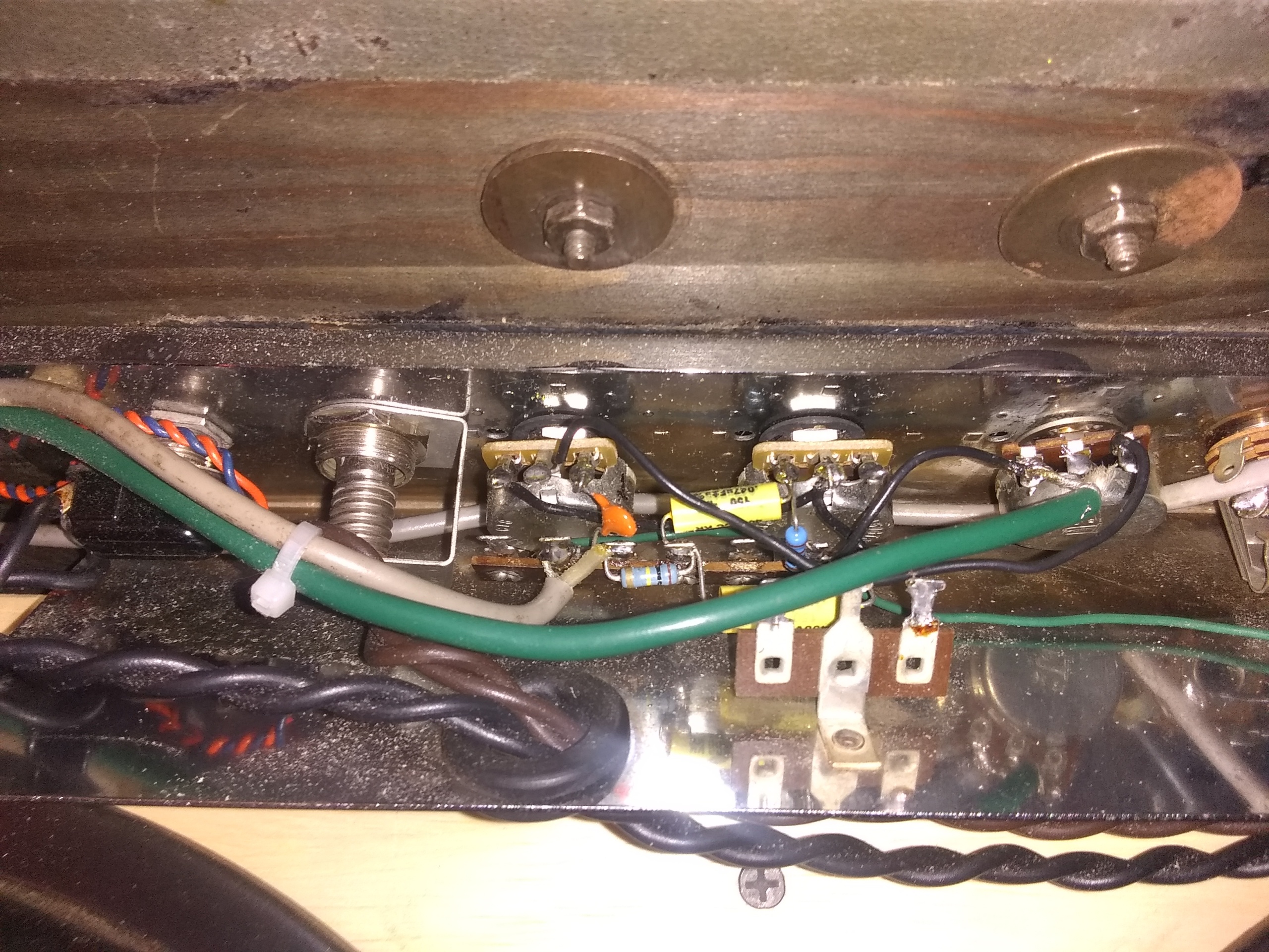
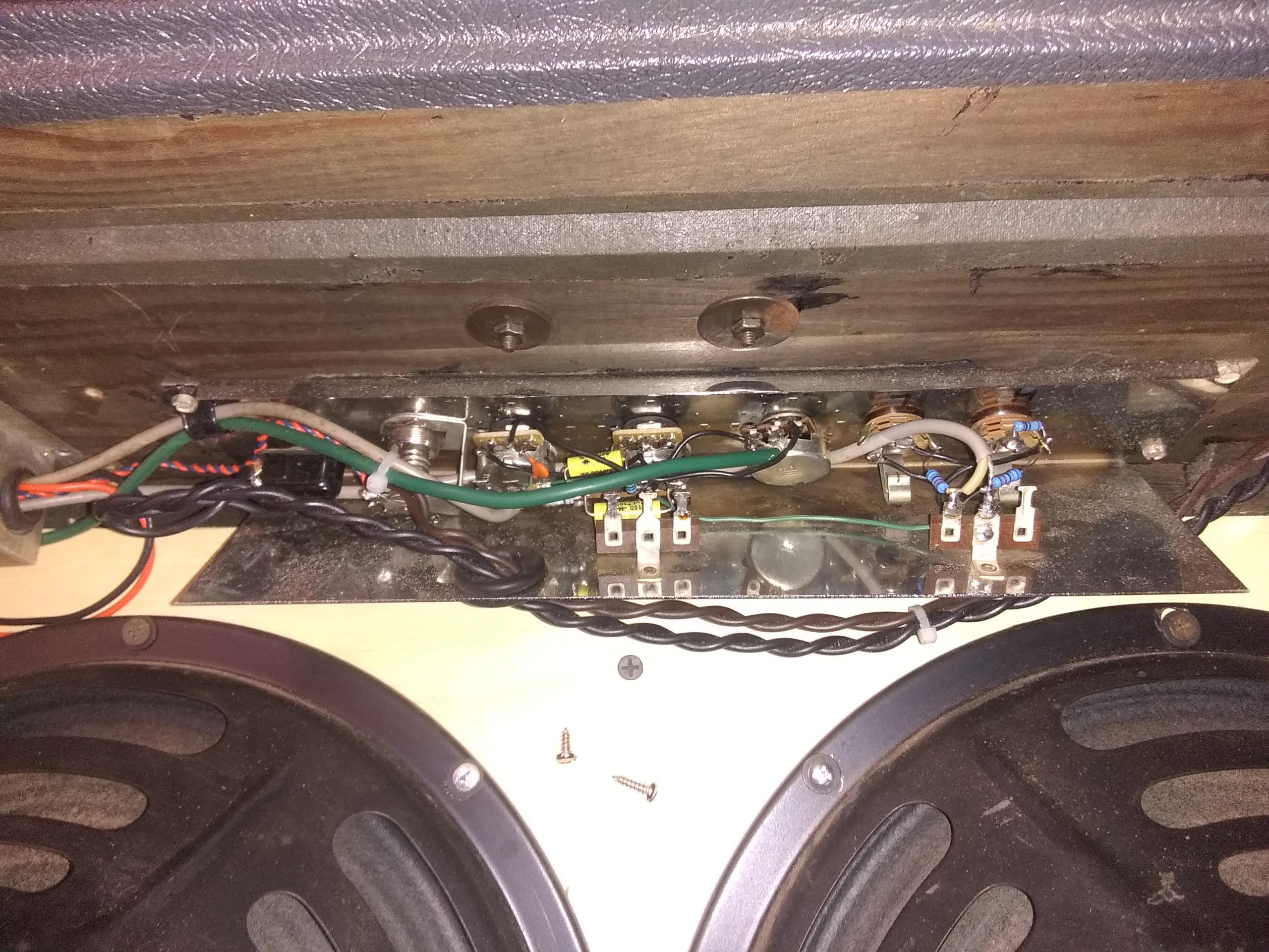
- Control panel rewired
- -Reversed mounting position.
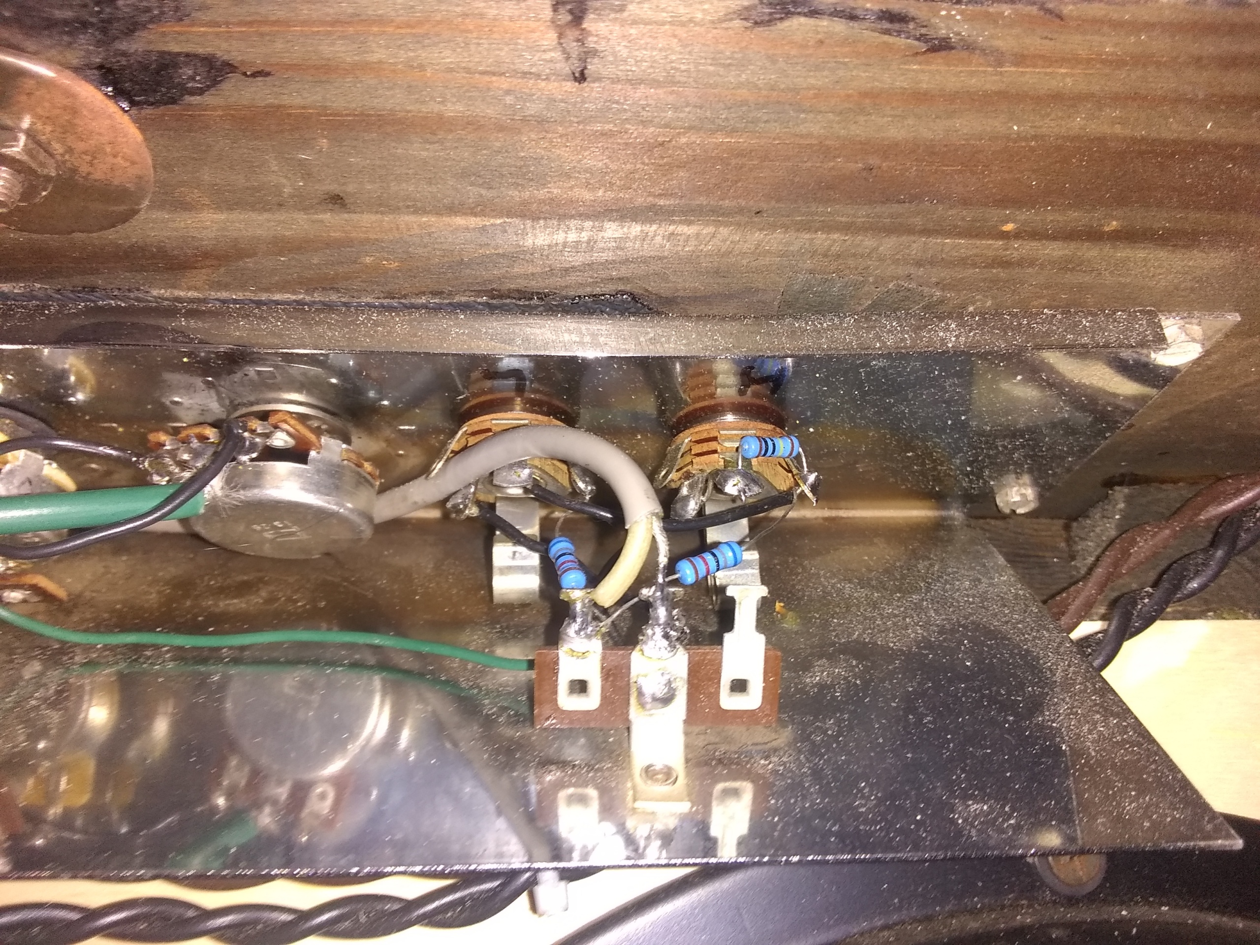
- -Fender-style tone stack built directly on pots.
- -Input section modified for guitar.
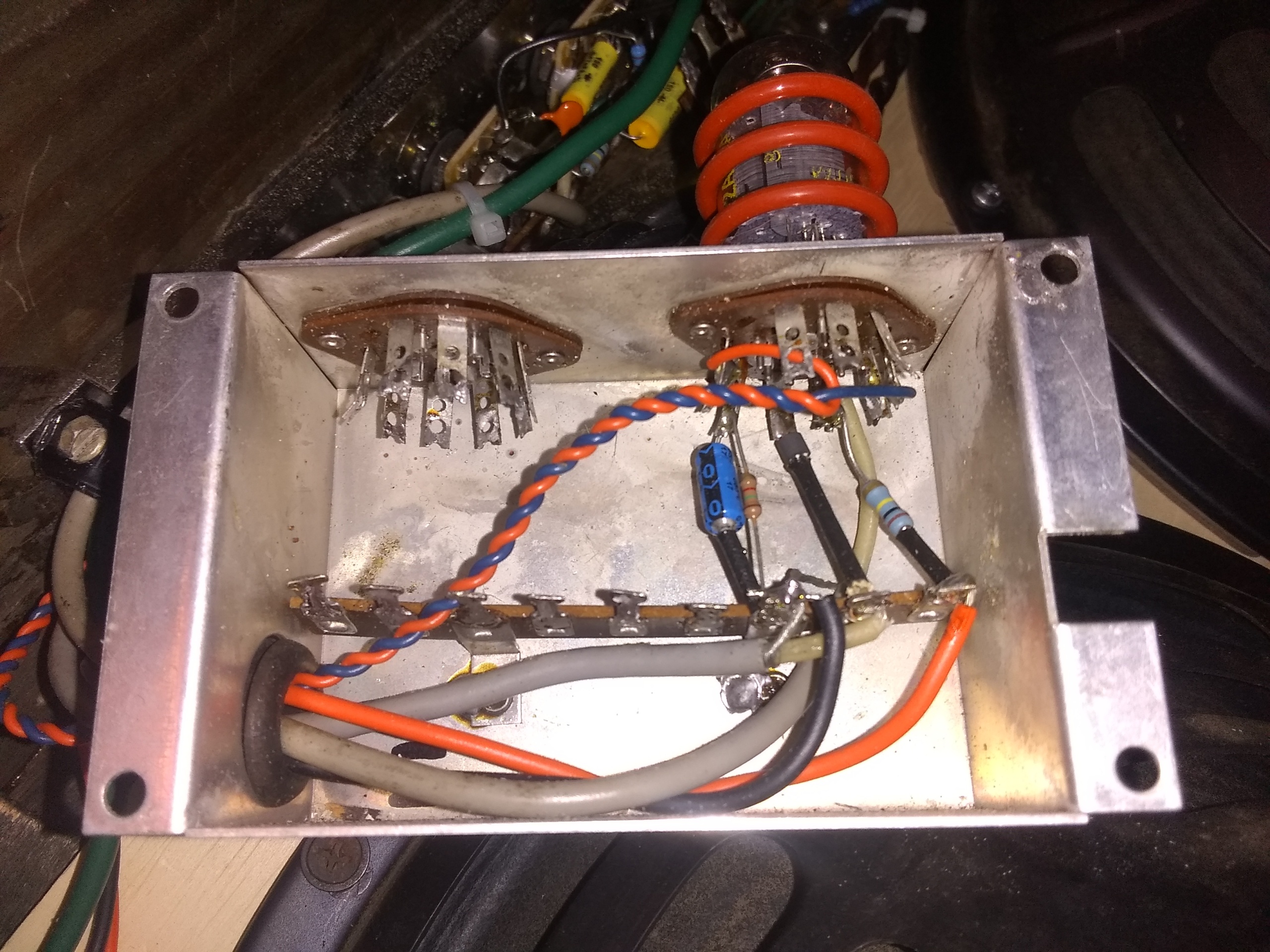
- Preamp Box removed from tone generator board.
- -Mounted next to control panel
- -Preamp circuit built to new specs.
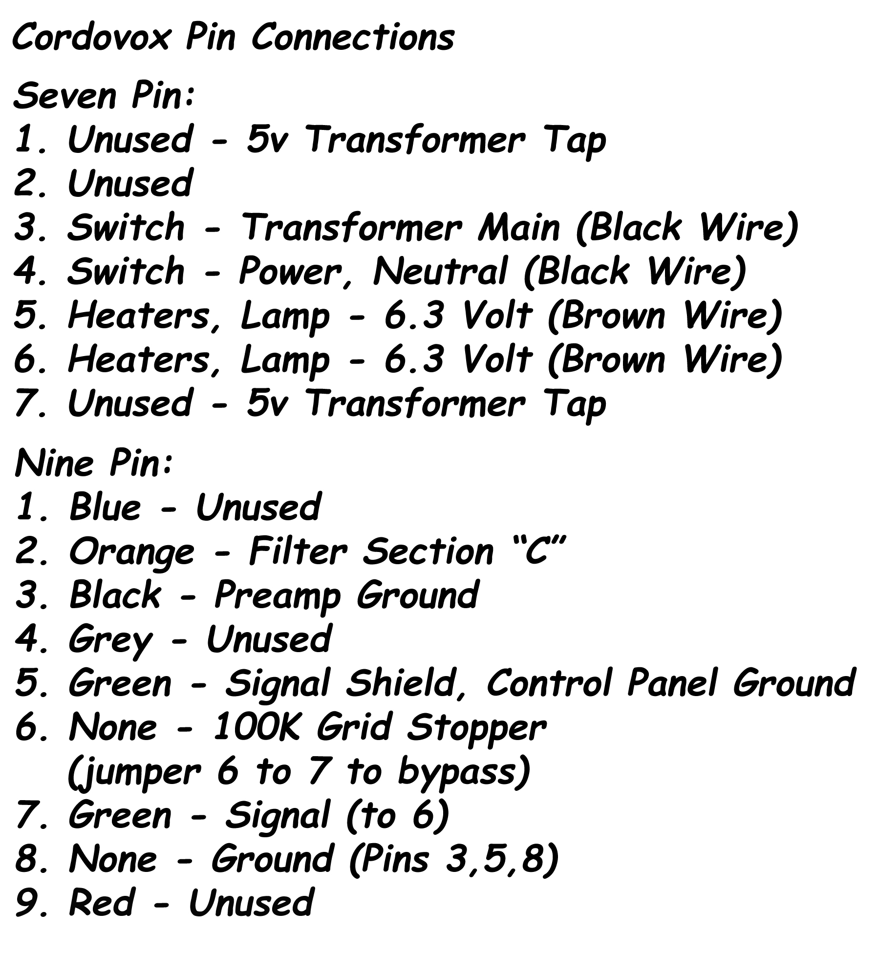
- Connector harness modified.
- -Sections divided
- -Split and routed to preamp and control panel.
- -Connector Pin Connections:
Circuit schematic:
A few notes:
As a standard disclaimer, I’ll note that this schematic is of my own design. Although the amp truly sounds amazing, I don’t consider this work to be perfect or final.
The result is an impressive sounding amp with the solidly vintage character reminiscent of 7591 amps, such as the early Ampegs and Premiers.
During the process of converting the Cordovox Accordion Amp, I tried to retain as much of the intent of the original circuit as practical while incorporating many of the classic elements of tube amp design. Following good practice, such building blocks can, of course, be adapted to taste.
One of the unusual remaining features of the original Cordovox circuit is the negative feedback loop that returns to the second stage preamp tube instead of the phase inverter as is typical. As kudos to the original amp design and as an experiment, I’ve left it that way. It works and the amp sounds great. Note that the negative feedback resistor value and has a pronounced effect on tone and can be changed to taste. I settled on a 100k resistor here in lieu of the original 39k.
After having rebuilt the power section true to the original Cordovox design I found amp voltages to run slightly high, especially during the initial startup surge. Unchecked, these higher voltages have the potential for putting undue strain on the power section. Several factors contribute to the high transformer output, namely hotter modern voltages and reduced transformer loading. Much of the original load the power transformer had to support became extraneous to the conversion. Caps rated at 500v would be best suited to handle the inrush current surge at startup, but the addition of two CL-60 thermistors in series reduced the inrush current to acceptable levels for 450v caps and also provided a satisfying seven volt steady state reduction (2%) to the B+ voltage. For startup voltages ranging higher than 450v, a simple bucking transformer similar to the design by Rob Robinette, would be a viable consideration.
Another major alteration to the original amp’s design was the bias circuit. This circuit was redesigned to incorporate a bias potentiometer, now added to the chassis. All component values were selected to put the fixed (adjustable) bias in a proper range. The elevated ground for the bias network was also simplified with no noticeable addition of noise.
The tone stack I’ve incorporated is of traditional design (Fender Champ, AA764). In my opinion, it fits the character and physical topology of the amp quite nicely.
Because the preamp section is mounted remotely, I felt it was important to keep the possibility of stray noise to a minimum. Following best tube amp building practices, the preamp box is mounted as close to the input jacks as possible. Note the ferrite choke (L2) at the preamp tube grid on the schematic. All wiring runs are tightly twisted, and well shielded where practical. Within the amp chassis, all grounding follows star grounding practices. The result of these efforts is a quiet, noise-free amp.
Cordovox Amp